Cite as:
Saad, T. "Solving Differential Equations with Mathematica - Roundup".
Weblog entry from
Please Make A Note.
https://pleasemakeanote.blogspot.com/2008/05/solving-differential-equations-with_29.html
Please Make a Note is a collection of science & technology tips and derivations that will make it easier for research scientists & engineers to perform the various tasks they are faced with. These notes cover a wide range of scientific topics, software, media, and data analysis utilities.
Wednesday, May 28, 2008
Solving Differential Equations with Mathematica - Roundup
Solving Differential Equations with Mathematica - Part IV: Equation Trekker
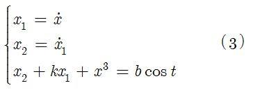
Since we can only use a single ODE, I will employ Ueda's oscillator model for illustration. The governing ODE is given by
 Here's the EquationTrekker code in Mathematica to generate the Poincaré section for Ueda's equations
EquationTrekker[{x''[t] + k x'[t] + x[t]^3 == B Cos[t]}, x, {t, 0, 10000}, PlotRange -> {{-5, 5}, {-5, 5}}, TrekParameters -> {k -> 0.3, B -> 11.5}, TrekGenerator -> {PoincareSection, "SectionCondition" -> Mod[t, \[Pi]], "SectionVariables" -> {x, x'}, MaxSteps -> \[Infinity]}]
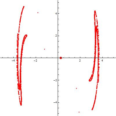
Voila!
Once the equation trekker interface opens, you have to click on the little pencil icon at the top and then click inside the plane to specify the initial conditions. Of course, there's much more to say about equation trekker, but I leave that for your curiosity. To change the sampling interval (more or less points), just modify the integration range specified by t. The sampling frequency is specified by the "SectionCondition".
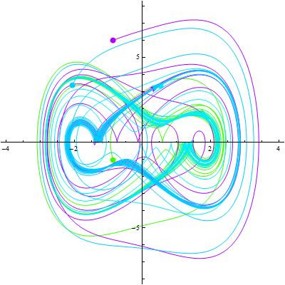
One can also easily generate the phase space using equation trekker. All you have to do is remove the TrekGenerator specification from the code given above, i.e.
EquationTrekker[{x''[t] + k x'[t] + x[t]^3 == B Cos[t]}, x, {t, 0, 100}, PlotRange -> {{-7, 7}, {-8, 8}}, TrekParameters -> {k -> 0.3, B -> 11.5}]
Download Mathematica notebook [right click / save as]
Cite as:
Saad, T. "Solving Differential Equations with Mathematica - Part IV: Equation Trekker".
Weblog entry from
Please Make A Note.
https://pleasemakeanote.blogspot.com/2008/05/solving-differential-equations-with_28.html
Sunday, May 25, 2008
Solving Differential Equations with Mathematica - Part III: Frequency Domain
(* Generate a table containing the numerical solution *)Voila!
yvalues = Table[(x[t] /. s1)[[1]], {t, Tend}];
(* Apply a discrete Fourier transform on that data and plot it*)
ListLinePlot[Abs[Fourier[yvalues]], PlotRange -> All]
Download Mathematica notebook [right click / save as]
Cite as:
Saad, T. "Solving Differential Equations with Mathematica - Part III: Frequency Domain".
Weblog entry from
Please Make A Note.
https://pleasemakeanote.blogspot.com/2008/05/solving-differential-equations-with_25.html
Friday, May 23, 2008
Solving Differential Equations with Mathematica - Part II: Phase Space
To generate the 2D phase space, use this simple code
ParametricPlot[Evaluate[{x[t], y[t]} /. s1], {t, 0, Tend}, PlotRange -> All]
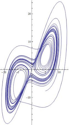
To generate the 3D phase space, use the ParametricPlot3D[] as follows
ParametricPlot3D[Evaluate[{x[t], y[t], z[t]} /. s1], {t, 0, Tend},PlotRange -> All]
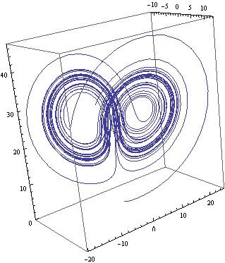 Voila!
Download Mathematica notebook [right click / save as]
Cite as:
Saad, T. "Solving Differential Equations with Mathematica - Part II: Phase Space".
Weblog entry from
Please Make A Note.
https://pleasemakeanote.blogspot.com/2008/05/solving-differential-equations-with_24.html
Thursday, May 22, 2008
Solving Differential Equations with Mathematica - Part I: Time Series
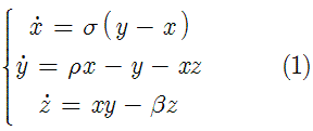 where x, y, and z are functions of time and sigma, rho, and beta are control parameters determined a priori. One could implement a fourth order Runga-Kutta method with adaptive time stepping to solve the above set of equations (and I would really recommend doing that). But in this article, we will use Mathematica which offers a super neat function called NDSolve[] that performs the numerical integration of ODEs. Without further adue, only a couple of lines of code are required in Mathematica to solve the above system of equations
(* Define control parameters *)Voila!
\[Sigma] = 3; \[Beta] = 1; \[Rho] = 10;
(* Define initial conditions for later use *)
x0 = 0; y0 = 1; z0 = 1;
(* Define interval of integration *)
Tend = 20 \[Pi];
(* Lump the initial conditions in one variable *)
initialConditions = {x[0] == x0, y[0] == y0, z[0] == z0};
(* Lump the Lorenz equations in one variable *)
LorenzEquations = {x'[t] == \[Sigma] (y[t] - x[t]),
y'[t] == \[Rho] x[t] - x[t] z[t] - y[t],
z'[t] == x[t] y[t] - \[Beta] z[t],
initialConditions};
(* Use NDSolve to integrate the Lorenz equations *)
s1 = NDSolve[LorenzEquations, {x[t], y[t], z[t]}, {t, 0, Tend}, MaxSteps -> \[Infinity]];
(* Plot the solution *)
Plot[Evaluate[x[t] /. s1], {t, 0, Tend}, PlotRange -> All]
Note that \[Sigma] will automatically convert to the greek symbol sigma. The same applies for the rest. You can also generate the greek letters by pressing escape, typing a letter on the keyboard, and then pressing escape. For example, escape, s, escape will turn into sigma.
Going back to the previous code, the two important statements are the NDSolve[] and the Plot[Evaluate[]].
In the first one, we are solving the Lorenz equations for x[t], y[t], and z[t] from t = 0 to t = Tend with an infinite number of time steps (MaxSteps->Infinity).
As for the Plot[Evaluate[]], the "x[t] /. s1" means replace all x[t] with the data contained in s1, which holds the results of the numerical integration. One could have also chosen to plot y[t] or z[t].
For first or higher order ODEs, it is advisable to get rid of all derivatives by definig them as new variables. This will be helpful for phase space diagrams to be discussed in the next article. For example, if you have the following system (Ueda's oscillator)
 it can be converted to
Download Mathematica notebook [right click / save as]
Cite as:
Saad, T. "Solving Differential Equations with Mathematica - Part I: Time Series".
Weblog entry from
Please Make A Note.
https://pleasemakeanote.blogspot.com/2008/05/solving-differential-equations-with.html
Wednesday, May 21, 2008
Importing Vertex Data in Gambit
Next, I had to figure out a way of input all the vertex data in Gambit. Obviously, it is very bad practice to input the data points one at a time. Being new to Gambit and CFD in general, my options were limited. Eventually, inputing the vertex data into Gambit turned out to be as easy as boiling eggs.
Voila!
- Get the vertex data ready in a text file
- In Gambit, File->Import->Vertex Data
Note that if the data is two dimensional, the text file will have only two columns. Gambit, however, assumes this is 3D data and will mess things up. What you have to do in this case is add a third column to the data file and fill it with "0.0". You can do that manually, or write a code to do that for you. I've written a tiny application in C# that will append a value that you specify at the end of every line of a text file. You can download it from here.
Cite as:
Saad, T. "Importing Vertex Data in Gambit".
Weblog entry from
Please Make A Note.
https://pleasemakeanote.blogspot.com/2008/05/importing-vertex-data-in-gambit.html
Tuesday, May 20, 2008
Vector (Nabla) Operations in Curvilinear Coordinates
Dot and cross products are invariant under coordinate transformation, so they have the same form for all coordinates
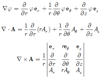
P.S. most people refer to the "inverted triangle" operator as the "del" operator; however, this symbol is called "nabla" just like epsilone, eta, gamma etc... and I find no reason for calling it otherwise! Therefore, I usually use terms such as "nabla phi" for the gradient of a scalar, "nabla dot A" and "nabla cross A" for the divergence and curl of a vector field, respectively.
Cite as:
Saad, T. "Vector (Nabla) Operations in Curvilinear Coordinates".
Weblog entry from
Please Make A Note.
https://pleasemakeanote.blogspot.com/2008/05/nabla-operations-gradient-curl-and-dot.html
Convenient Form of the Navier-Stokes Equations
Most of us learn the fundamentals of fluid mechanics using Cartesian coordinates. Specifically, derivations of the Navier-Stokes equations are done in a Cartesian reference system. This is a valid way for studying such a complicated set of equations as rectangular coordinates do not present us with the nuances of extra terms due to curvature or other effects that are present in curvilinear coordinates. The final form for the momentum equations is concisely written in vector notation for compactness and simplicity. This is given by
I would like to thank Prof. Gary Flandro of UTSI for promoting the use of this form.
Cite as:
Saad, T. "Convenient Form of the Navier-Stokes Equations".
Weblog entry from
Please Make A Note.
https://pleasemakeanote.blogspot.com/2008/05/convenient-form-of-navier-stokes.html
Monday, May 19, 2008
Invariant Form of the Navier-Stokes Equations
Cite as:
Saad, T. "Invariant Form of the Navier-Stokes Equations".
Weblog entry from
Please Make A Note.
https://pleasemakeanote.blogspot.com/2008/05/invariant-form-of-navier-stokes_20.html
Sunday, May 18, 2008
Interactive Plots in Mathematica
Manipulate[Plot[Exp[-w x] Cos[a x], {x, 0, 3 Pi}, PlotRange -> Full], {w, 0, 10}, {a, 0,20}]Voila!
For a complete description of the Manipulate function, you can visit its Mathematica documentation page
http://reference.wolfram.com/mathematica/tutorial/IntroductionToManipulate.html
Cite as:
Saad, T. "Interactive Plots in Mathematica".
Weblog entry from
Please Make A Note.
https://pleasemakeanote.blogspot.com/2008/05/interactive-plots-in-mathematica.html
Saturday, May 17, 2008
Optimize Fluent Simulations
Grid->Reorder->DomainVoila!
Cite as:
Saad, T. "Optimize Fluent Simulations".
Weblog entry from
Please Make A Note.
https://pleasemakeanote.blogspot.com/2008/05/optimize-fluent-simulations.html
Animations in Mathematica
A good way of presenting your work is to use animations. This is true when you have an analytical model where you need to explore the behavior of the solution under a change of certain control parameters. There's an easy way of doing this using Mathematica. Here is a sample code in mathematica
(* Define function to be animated *)The animation will look like this
f[x_, L_] = Cos[L*x];
(* Create a table of plots *)
theTable = Table[ Plot[{f[x, L]}, {x, -4, 4}], {L, 1, 10}];
(* Export this table into an animated GIF - Replace gif with swf to export as a flash swf file*)
Export["C:\\TestAnimation.gif", theTable, ImageSize->350];
Voila!
(* Define functions to be animated *)The animation in this case looks like this
f[x_, L_] = Cos[L*x];
g[x_, L_] = Sin[L*x];
(* Create a table of plots *)
theTable = Table[ Plot[{f[x, L], g[x, L]}, {x, -4, 4}], {L, 1, 10}];
(* Export this table into an animated GIF - Replace gif with swf to export as a flash swf file*)
Export["C:\\TestAnimationCombo.gif", theTable, ImageSize->350];
Download Mathematica notebook [right click / save as]
Cite as:
Saad, T. "Animations in Mathematica".
Weblog entry from
Please Make A Note.
https://pleasemakeanote.blogspot.com/2008/05/create-mathematica-swf-animation.html
Friday, May 16, 2008
Fluent Axisymmetric Simulations
To run an axisymmetric simulation in Fluent you have to do the following
- In Gambit, make sure your axis of symmetry is aligned with the x-axis (i.e. y = 0)
- Set the axis edge as an "axis" boundary condition
- Once you import your mesh into Fluent, set the solver to Axisymmetric
Voila!
Cite as:
Saad, T. "Fluent Axisymmetric Simulations".
Weblog entry from
Please Make A Note.
https://pleasemakeanote.blogspot.com/2008/05/fluent-axisymmetric-simulations.html
Thursday, May 15, 2008
Fluent Graphics Display in Remote Desktop Mode
- Display->Options
- Uncheck "Hidden Surface Removal"
Cite as:
Saad, T. "Fluent Graphics Display in Remote Desktop Mode".
Weblog entry from
Please Make A Note.
https://pleasemakeanote.blogspot.com/2008/05/fluent-graphics-display-in-remote.html
Wednesday, May 14, 2008
Set Column Values in Origin
- Select the first column by clicking on its title label
- Right click and invoke the "Set Values" dialog box
- Click on the little arrow to the bottom right (called "Show Scripts")
- In the "Before Formula Scripts" text box, type in the following
// Get index of current column
const nn = _ThisColNum;
// Perform numerical operations on this column
wcol(nn) /= 10;
- Click apply
- Select the formula and copy it (Ctrl + c)
- Now go to the next column by clicking on the Next Column button (or simply selecting another column)
- Paste the formula (Ctrl + v) and click apply
Cite as:
Saad, T. "Set Column Values in Origin".
Weblog entry from
Please Make A Note.
https://pleasemakeanote.blogspot.com/2008/05/set-column-values-in-origin.html
Tuesday, May 13, 2008
Enable LES (Large Eddy Simulation) in Fluent 2D
(rpsetvar 'les-2d? #t)Voila!
This will enable LES in 2D models. Note that turbulence is inherently a 3D phenomenon and using LES for two dimensional flows is not recommended. However, in certain cases such as code benchmarks or debugging, it is useful to run LES in 2D. I would also speculate that LES is a valid model in axisymmetric conditions.
Cite as:
Saad, T. "Enable LES (Large Eddy Simulation) in Fluent 2D".
Weblog entry from
Please Make A Note.
https://pleasemakeanote.blogspot.com/2008/05/enable-les-large-eddy-simulation-in.html
Monday, May 12, 2008
Automatically convert hyperlinks in MS Outlook 2008
http://www.blogger.com/
Of course, it would be nicer if an internet address is automatically converted into a hyperlink, i.e.
http://www.blogger.com/
Outlook can do this automatically instead of manually converting each address into a clickable hyperlink. Here's how to do it:
Voila!
- go to: Tools -> Options
- Click on the "Mail Format" tab
- Click on "Editor Options" at the bottom of the options dialog (this will bring up the "Editor Options" dialog)
- Click on the "Proofing" tab to your left
- Click on "AutoCorrect Options"
- Select "Internet and network paths with hyperlinks" in the "Replace as you type" section
Cite as:
Saad, T. "Automatically convert hyperlinks in MS Outlook 2008".
Weblog entry from
Please Make A Note.
https://pleasemakeanote.blogspot.com/2008/05/automatically-convert-hyperlinks-in-ms.html
Things to remember...
To make things easy (and in case you want to skip the reading as we all do when we are looking for a computer trick),
all the steps or codes required to achieve a certain task are typed in bule and placed in a dashed rectangleIn any event, I hope you find something useful on this blog. I would appreciate any comments.
Peace.
Cite as:
Saad, T. "Things to remember...".
Weblog entry from
Please Make A Note.
https://pleasemakeanote.blogspot.com/2008/05/things-to-remember.html
